Neutron Star 3 Audio Clock
닫기*구입전 필독사항*
AUDIO DIY는 위험 부담을 알고 자신의 책임하에 제작, 개조 및 수리 등을 하는 것입니다.
DEXA제품은 출고시 완전히 TEST되어 판매되는 제품이므로 구입제품을 개봉한 후 생기는 문제에 대해서는
어떠한 이유로도 교환 또는 반품이 되지 않으니 이점 양지하시기 바랍니다.
주요기기 모델별 상세 장착법 (새창으로 띄우세요)
(L Clock 장착법입니다만 D-Clock에도 거의 동일합니다)
*** 꼭 참조하세요 ***
가끔 Clock 주파수 변경 의뢰가 들어오는 경우에 보게되는 현상입니다.
좋은 부품이라고 D-Clock이나 Neutron Star의 부품을 교체한 경우가 많습니다.
적절한 조치없이 무조건 좋다는 부품으로 교체한 경우 그 효과를 절감시키거나
오히려 역효과를 낼 수 있습니다.
Dexa의 clock은 매우 정교하게 setting되어 있습니다. 조금의 부품의 정전용량이나
시정수의 변화에 따라 기존 setting이 틀어져 버립니다. 실제 업그레이드한 Clock의
주파수를 측정해보면 실제 주파수와 매우 달라져 있는 것을 많이 발견합니다.
검교정을 거친 매우 정밀한 주파수카운터로 재 setting하지 못하는 경우 이러한 부품의
업그레이드나 회로상의 변경은 지양해 주시기 바랍니다.
.jpg)
*** 전원선은 flat cable 4가닥중 2가닥씩 나누었을 때 +는 색깔이 없는 쪽, -는 파란색 색깔쪽입니다.
위의 사진을 참조하세요시어.
*** 꼭 참조하세요 ***
| 가끔 Clock 주파수 변경 의뢰가 들어오는 경우에 보게되는 현상입니다. 좋은 부품이라고 D-Clock이나 Neutron Star의 부품을 교체한 경우가 많습니다. 적절한 조치없이 무조건 좋다는 부품으로 교체한 경우 그 효과를 절감시키거나 오히려 역효과를 낼 수 있습니다. Dexa의 clock은 매우 정교하게 setting되어 있습니다. 조금의 부품의 정전용량이나 시정수의 변화에 따라 기존 setting이 틀어져 버립니다. 실제 업그레이드한 Clock의 주파수를 측정해보면 실제 주파수와 매우 달라져 있는 것을 많이 발견합니다. 검교정을 거친 매우 정밀한 주파수카운터로 재 setting하지 못하는 경우 이러한 부품의 업그레이드나 회로상의 변경은 지양해 주시기 바랍니다. |
.jpg)
| Accuracy at 25 deg C: | +/- 1ppm. |
| Accuracy from 20 to 50 deg C: | +/- ppm. |
| Jitter: | 1.0pS RMS (10 Hz - 50 kHz range). |
| Frequency Deviation(8-24V): | Max 1Hz. |
| Power Supply (Optimal): | 15.00 Volts DC 150 mA. |
| Power Supply Recommended: | 12.00 - 20.00 Volts DC 150 mA. |
Ultimate Performance Audio Reference Clock with Gallium Nitride voltage reference.
| This reference clock is placed inside your CD player, DVD or Blu-ray player, asyncronous D/A Converter, USB receiver, audio PC motherboard or other clocked digital audio equipment. It has the potential to drasticly improve the sound quality of your digital audio equipment. Every digital audio equipment is already clocked from the factory, however most of the times this clock is a cheap and noisy type, based on CMOS gates or a noisy 7805 regulator, or most likely both. In the D/A Converter of your digital player, the voltage reference determines the S/N ratio when the output signal is a stable DC voltage. However when the signal is in transient, the voltage reference becomes less important, and it is now the clock source that | determines the S/N ratio. If there is too much noise you hear it as a narrow and flat sound stage. Therefore it's surprising that so few OEMs seem to offer much energy on this point. We do, and you can fit this clock source inside your equipment, and get immediate improvement. We have two different clocks, the Neutrino, a small form factor and low cost clock with still decent performance. And for ultimate performance we have the Neutron Star 2, a hand adjusted precision clock, with temperature control, and an abundance of support features to get ultimate performance from your digital sound equipment. Clock and power supply cables are included. |
How does it affect the sound?
| A reference Clock is installed inside an audio player, and will have the effect of cleaning up the sound stage. This means the sound stage will spread out correctly, and make it easy for you to feel where the instruments and artists are placed. It essentially turns music from background noise to a living experience. Most digital audio equipment is fitted with a noisy clock from the factory, running on the same power rail as the rest of the (noisy) electronics. This will give a narrow and blurry soundstage. Kind of like if the whole band in your music were standing inside a phone booth, and you were trying to listen outside. | You cannot pinpoint if the drums are in front or back. So there is potential for improvement. A reference clock is step #1 in upgrading a digital player, to reach clean and living digital sound, which will let you really enjoy the music instead of turning it down. You can apply a reference clock to a cheap or expensive player with the same positive result. We guarantee you, that you will be surprised and amazed how much improvement in sound you can get from this clock. |
A whole new type of Voltage Reference.
| The voltage reference is the most important part for making the clock's performance. If the reference has any noise, it will find it's way into the clock signal, which will lower the performance. In our previous clock regulators we used the LM329, one of the best single chip voltage references in the world, when it comes to low frequency noise performance. But there are ways to push the noise level even lower, but it takes some effort. A special type of green LED, based on a Gallium Nitride crystal has been found to have exceptional low noise, but unfortunatly also lower temperature stability. Therefore we spent a lot of research trying to find a way to compensate for the temperature drift of the Gallium Nitride crystal, without sactificing any noise performance. So we ended up with a total of 63 components to replace just the one LM329 chip, with the sufficient | stability and noise rejection. This while keeping the extreme good noise performance of more than 30 times better than a standard 7805 regulator. Can the noise performance be achieved by using decoupling capacitors? This seems like a logical and cheap solution, but that would only work at higher frequencies like above 100 Hz, while the most hostile noise is in the lower frequencies. Therefore there are no available standard references with low enough noise, to achieve the outstanding performance that has now been achieved with Neutron Star 2. The noise is so low, that a capacitor will not even improve the noise, and therefore we didn't use the OSCON capacitors we used in the earlier version. They have no effect in this reference. |

The residual noise of the Gallium Nitride reference. (-90dB)

Compared to the same measurement for a 7805 standard regulator. (-62dB)
Note the scale is different on the two readings, and the noise in both readings are amplified 1000 times or 60dB. So the absolute values are -130dB and -102dB under 2.83V respectively.
Temperature stability and support features.
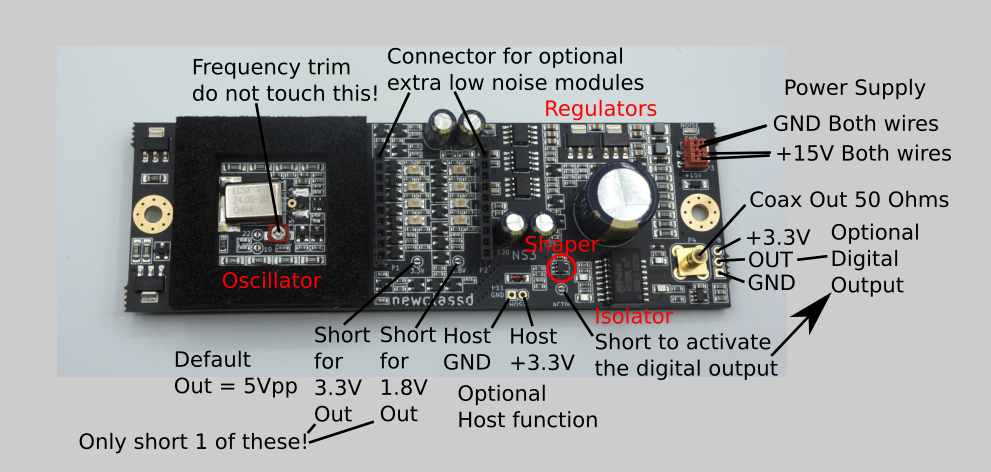
| The Neutron Star 2 has an on-board stabilized temperature island, which will keep the frequency stable at all normal environmental conditions. When the thermostat is locked, a green LED will turn on, indicating the right temperature of the crystal has been reached within +/- 0.5 deg. C. At the 15V power supply connector there is a small red LED which will light up in case any noise is detected on the power supply line. This is measured before the on-board regulators, and may not affect the performance of the clock, however you have a warning to let you know something should possibly be done to remove noise on the power supply. There is a HOST function on the NS2 clock. Let's say you have an external power supply for the Neutron Star 2 (recommended), and it will run with power continously. But maybe your DAC or digital player is not always on. Then you need to switch the clock off whenever the digital player is off. This can easily be done with the HOST function. Simply connect the 3.3 or 5V supply of the host player to the NS2 HOSt terminal, and activate the HOST function (see instructibles). Then the clock will only be active on the output whenever the player is on. | The output clock amplitude has to fit with the host machine, therefore a setting is possible on each clock, to get 5V (default), 3.3V or 1.8V (for Raspberry Pi3) clock amplitude. The NS2 has 2 different outputs, and they are completely isolated from each other, and from the power supply plug (by at least 300V AC potential). The main output is a 50 Ohms COAX output, which is potential shifted to the set positive voltage. This signal connects to the input of the clock gate on the host board. The Active output is the same clock signal, but the first gate is actually placed on the NS2 board, giving in some cases a better compatibility to the host (and thus better sound in some cases). This might be used in cases where the host player uses a metal can oscillator. Here you connect 3.3 or 5V DC from the host supply to the NS2 Active output, and then you have a CMOS compatible digital clock output signal, just like the metal can oscillator. But in this case you can only run up to 5-7 cm. of wire to the player. Better 3 cm if possible. |

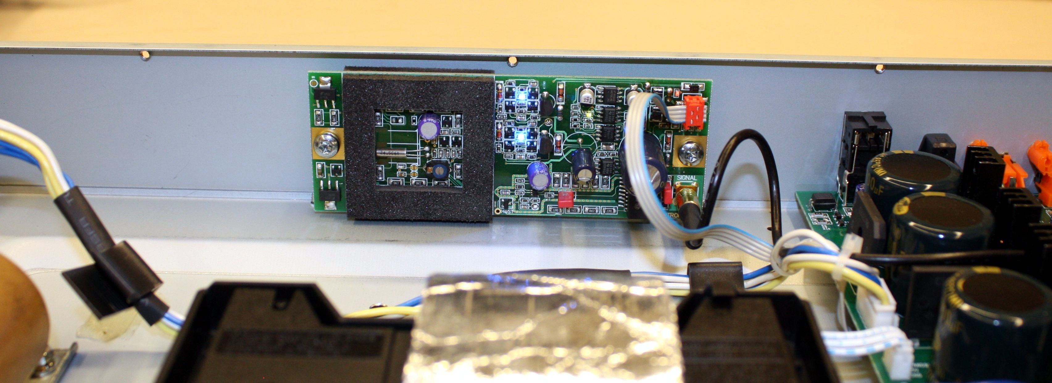
Low Noise Colpitts Oscillator.
| The Neutron Star 2 Clock uses a Colpitts oscillator, famous for low noise, and usually found in sensitive receiver equipment. This type of oscillator does not transfer power rail noise to the clock phase, like a standard oscillator based on the simpler and more noisy Pierce type '74HCU04 inverter' oscillator, as found in most OEM equipment. Not only is the gate not exactly a low noise amplifier for weak crystal signals, but also half of the noise on the +5V rail is coupled directly on top of voltage on the input pin. But it is cheap, and therefore used many places. | In Neutron Star 2 we go another way, and try to make the best possible product, without compromising on important places. A new special performance feature, compared to earlier versions is that we no longer use a silicon RF transistor in the oscillator, but now instead a germanium ultra low noise transistor. This type of transistor is extremely stable, and normally used in professional GPS receivers. |
Transformer isolated injection point.
To understand why this feature is an absolute must in a quality clock, we can compare the install circuit with and without isolated output.

| The clock installation of a typical clock with direct output will form a GROUND LOOP, causing noise from all the circuits in the host machine to most likely connect through the clock signal wire. This destroys the clock unit's performance. In the Neutron Star 2 we use ground isolation (up to 1500V AC) to eliminate | the ground loop. Now only a very weak current flows in the ground wire, and the noise problem is eliminated. The ground of the clock gate in the host machine may still have some noise on it, however this becomes common mode noise, and will not affect the clock signal. |

 | The actual transformers are tiny toriod's, inside an SMD package. |
Power Supply Connection.
Note the two GND wires are already connected on the board, so only one of the wires need to be connected externally, but both may be connected. The same goes for the two +15V wires. We recommend 15V DC supply voltage, however it can run on lower voltages, like 12V, but the thermostat becomes somewhat slower in achieving lock.

Click!
Clock Connection Normal.
The NS2 has two output options. The "Normal" COAX connected output that moves the clock signal in shielded cable. This cable should be kept as short as possible, but the clock signal will survive up to 50 cm. of wire, and will not get corrupted by airborne noise. You may use any of the two outputs as you find best, or even both. The two outputs are completely separated, and one can be connected to say the DAC while the other is running the transport.

Click!
The active clock is a digital clock output. It requires power supply voltage of 3.3V or 5.0V from the host machine, this way you are sure the voltage of the clock signal will match the host machine's requirement. The clock wire itself must be kept very short, for lower frequencies less than 10cm, and for higner frequencies, 3-4cm tops. The clock signal will not survive long stretches of wire in this configuration. On the other hand you may get a "cleaner" connection to your host machine if you can get the wire short enough.

Host Function.
Connect the HOST terminal to +3.3 or +5V of your host equipment. This allows the clock to see if your equipment is on or not.
Remove solder from the "IGNORE" pad, to activate the HOST function.
Now the clock will switch off whenever the host player is off.

Click!
Clock Voltage setting.
The Neutron Star 2 can deliver a clock signal of 1.8, 3.3 or 5V peak to peak. The default value is 5Vpp. If you require 3.3V (most modern equipment) then add solder to the pad labelled "3V3". For 1.8V output signal, add solder to the pad labelled "1V8". Only add solder to ONE pad at a time. If you wish to change the voltage, you can of course remove solder from whatever pad you have used before. No solder gives the default 5V output signal.

Click!
Neutron Star Generic Instructions
Click
Before you order.
| 1.. | Decide whether you want a tuning shop to perform the installation or you want to do it yourself. |
| 2.. | Disconnect the mains chord. CAUTION Risk of electric shock! |
| 3.. | Open your player. |
| 4.. | Identify the crystal. It should look like one of these: |
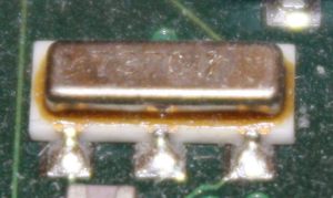 | 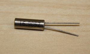 |
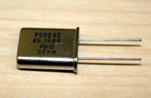 | 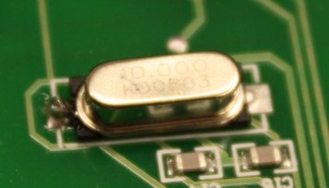 |
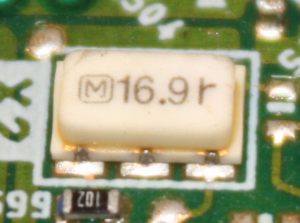 | 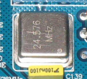 |
| The marking should correspond to one of the 'audio' frequencies on the frequency list: 8.467200 MHz 11.289600 MHz 12.288000 MHz 16.934400 MHz 22.579200 MHz 24.576000 MHz 27.000000 MHz 33.868800 MHz 45.158400 MHz These frequencies are all a multiplum of 44.1 or 48 kHz sampling frequency. For example 11.2996 MHz is 256 x 44.1 kHz. The marking may only be some of the digits, for example 16.934400 MHz, may be marked on the crystal simply as 16.9. But if you find a crystal marked with 4.00 or 10.700, you are looking at the wrong crystal. A player can have several crystal for various purposes. Also some players have a digital input, in this case, make sure you are not looking at the crystal from the digital input decoder. It makes no sense to upgrade that one with a clock, as it is turned off, once the chip has locked onto the signal. | |
| 5.. | Note the correct frequency and DAC or other chip that the crystal is directly connected to. |
| 6.. | Assemble your player again. |
| 7.. | Order the correct Neutron Star Reference Clock. |
| 8.. | Find the datasheet of the chip, that your crystal is directly connected to. [Here] is a good datasheet search machine. |
The Installation.
| 1.. | Disconnect the mains power. |
| 2.. | Open your player. |
| 3.. | Connect power, and turn on the power. CAUTION Risk of electric shock! |
| 4.. | If you were unable to find the correct datasheet of the chip your crystal was connected to, use this simple trick: Place a CD in the player, start playing at low volume. Touch each side of the crystal with a small screw driver, to determine which one makes the sound stop or scramble. The one side of the crystal which is more sensitive, is going to be your injection point for the clock signal from Neutron Star. Mark it up with a pen. 4b.. An alternative method to find the injection point is this: Remove the xtal. Connect the clock to any of the two xtal pins through a 1k resistor, and of course the shield of the coax cable to GND. (See pt. 14 below) Then if the machine will turn on, and function normally, then you have the right injection point, in the xtal pin you just used. If it does not start up and function normally, then try the other xtal pin. When you found the right pin, mark it up with a permanent marker. If you were able to find the datasheet, find the two pins of the chip, where the crsytal is connected. They will most likely be demoninated XI and XO in the datasheet. Or in case of a logic chip, like 74HC04 or alike, you will be able to read which pin is input and which one is output. You will use the input pin, or XI as injection point for the clock signal from NS. NOTE: Never connect the signal from the clock to one xtal pin, and then the GND to the other xtal pin. It may seem obvious, but we see this mistake all the time. :-) |
| 5.. | Now determine whether your player runs on 3V or 5V. This is easy. Measure the other terminal of the crystal with your multimeter. If it shows around 1.4V, your system runs on 3V. If it reads 2.4V it's 5V. Most aged players run on 5V, while newer players especially DVD players run on 3V. 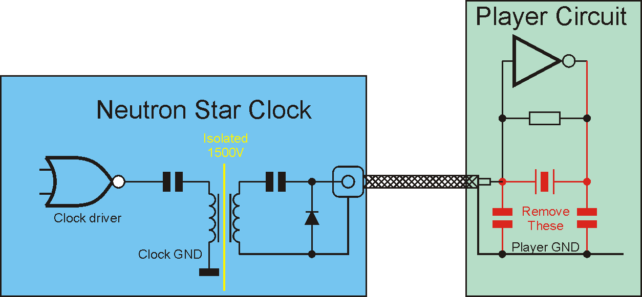 Click! This is the typical circuit, which will automaticly align itself to the right DC level. 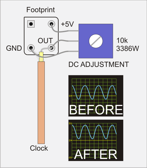 Click! In case the clock signal ports directly to a gate with no DC alignment, you should use a trimmer to make sure the DC level is correct. This is typically the case if the factory clock is a metal can oscillator (..and not a discrete crystal unit). 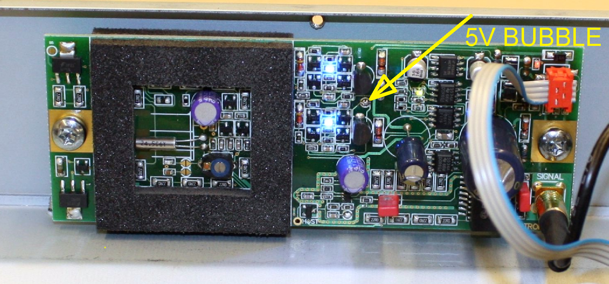 Click! In case your player has a crystal oscillator rather than a crystal, simply measure the voltage between the corner pins, it is most likely 5V, in which case it's a 5V system. |
| 6.. | Set the 5V solder bubble on Neutron Star, in case it's a 5V system. It's located right between the two blue LED's. |
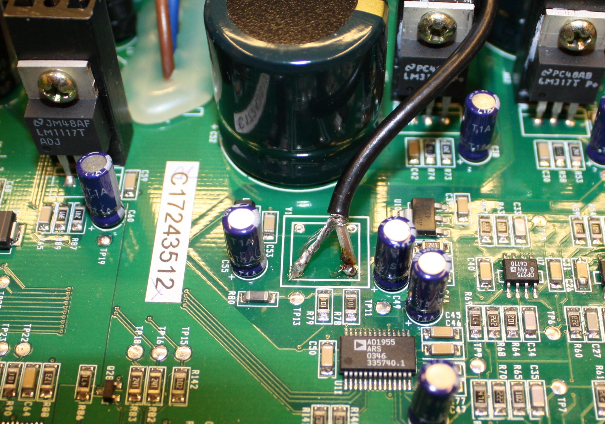
| 7.. | Use a multimeter to identify a good power source of 10 - 15V DC, with ground potential the same as the enclosure. You can check this by placing your test wires between the enclosure, and the terminal you want to use as GND for Neutron Star. It must show close to zero Volts. The best power source is on a large can electrolytic capacitor, such as the dark green ones you see on the photo above. Just make sure the voltage on the cap is between 10 and 15V. If you cannot find an appropriate power source, we recommend you use a separate power supply module of 12-15V DC 200mA or more. Preferably with low noise regulation. |
| 8.. | Turn the player off again, and remove the power cord. |
| 9.. | Find out where the Neutron Star module will fit inside your player. Mark up the holes for the two M4 screws, and drill them. Mount the module. |
| 10.. | Fit the signal cable on the clock module, lead it towards the crystal on the CD player's motherboard, and cut the cable in a fitting length. |
| 11.. | Remove screws holding down the PCB where the crystal is mounted. (Unless your crystal was of the SMD - surface mounted - type). Careful not to stress the wires and connectors. You may have to remove some of them, to get to the other side of the circuit board. In this case write down which wire goes into which connector. Or take a good picture of the whole thing before disassembling it. This way it's easy to assemble again. |
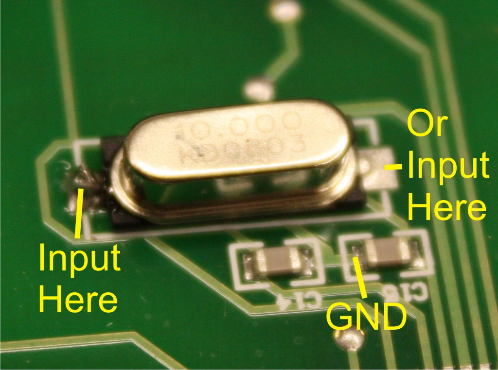
| 12.. | Unsolder the crystal. |
| 13.. | Remove insulation from the clock signal cable, and solder the inner wire onto the terminal of the crystal you marked up as injection point. |
| 14.. | Solder the outer wire (GND) onto GND. NOT onto the other crystal terminal. |
Click
You can identify a good GND at the point where the two capacitors on the crystal meet.
Click
Or in case of a crystal oscillator, simply use these terminals of the 4 pin can, for GND and injection.
Notes on installation:GND Potential.
|
| 15.. | Solder the Neutron Star power cable onto the electrolytic capacitor you identified as a good power source. The line marked wire of the cable is GND. |
| 16.. | Asseble the player again, with all the screws in position to hold down the motherboard. And remember to fit the player's connectors as well. |
| 17.. | Make sure both connectors are fitted correctly on the Neutron Star. |
| 18.. | Connect power to the player, and turn it on. |
| 19.. | Observe the two blue LED's turn on, to show that power is present. |
| 20.. | Make a test run with low volume, to make sure the player has accepted the new clock signal. |
| 21.. | If the red LED light up, it means your power source is contaminated with noise or ripple. The clock will still work correctly, but you may get some improvement if you use a good power supply instead. |
| 22.. | After a couple of minutes the green LED will turn on, to indicate that the Neutron Star has reached it's correct operating temperature of 37 degrees Celcius. |
| 23.. | Assemble the enclosure again. |
That's It!
Congratulations, you have upgraded your player. Best sound performance will reveal itself after 1-2 weeks of operation.Should you experience any problems with the installation, please contact me by e-mail: sales@newclassd.com.
Enjoy!

